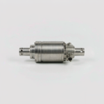
Dynamic torque is difficult to measure because the sensing element rotates with the shaft. The RT-200 solves this with inductive power coupling and a contactless digital transmission path, eliminating slip ring wear, brush noise and the maintenance that comes with them. The result is a clean torque signal at high rotational speed together with a separate speed pulse, allowing mechanical power to be calculated directly. Test engineers can log efficiency maps, start up transients and overload events from the same compact inline unit.
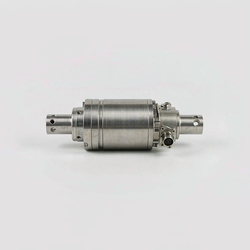
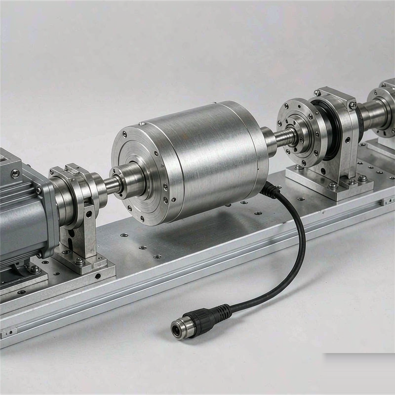
A torsion shaft of hardened stainless steel sits between two precision bearing supports inside a brushed stainless housing. Strain gauges are bonded at forty five degrees to the shaft axis in a full bridge, and the rotating electronics are powered across an air gap by a stationary coil. Shaft ends are keyed with optional clamping couplings; the stationary housing carries a multi pin connector, a status indicator and a mounting foot with slotted holes. An optional encoder disc adds higher resolution speed and angle information.
The 200 Nm range is measured with better than 0.2 percent of full scale accuracy and a bandwidth close to one kilohertz, so short torque peaks are captured rather than averaged away. Speeds up to 6000 rpm are supported in the standard bearing configuration, with a low starting torque that does not disturb small motors. Outputs can be specified as plus or minus 5 volts, 4 to 20 milliamps or RS485, and the internal temperature compensation keeps zero stable through long endurance runs. Overload stops protect the torsion element.
Align the sensor between the drive and the load with flexible couplings on both sides; rigid connections introduce parasitic bending that appears as torque ripple. Secure the housing to the baseplate so it cannot rotate, but leave the shaft free of axial thrust. Keep the stationary coil clear of metal brackets, use shielded cable for the analog output and set the data acquisition sampling rate above twice the expected torque frequency. Zero the channel with the shaft stationary and uncoupled before each test campaign.
Each transducer is supplied with a calibration trace taken in both rotation directions, a coupling selection guide and a protective shipping case. Output format, shaft end geometry and speed channel resolution are chosen at order entry because they affect the internal electronics. A separate display unit and a USB data logger are available for bench use. Lead time is longer for custom shaft ends, so the mechanical interface drawing should be confirmed early in the project.