High capacity drivetrain tests demand a transducer that survives continuous load while still resolving small efficiency differences. The RT-1000 combines a stiff torsion shaft with a non contact telemetry link and a built in encoder, so torque and rotational speed are measured on exactly the same shaft at the same instant. That pairing makes mechanical power and efficiency available as a direct calculation rather than a reconstruction from two separate instruments, which is essential when mapping a gearbox across many operating points.
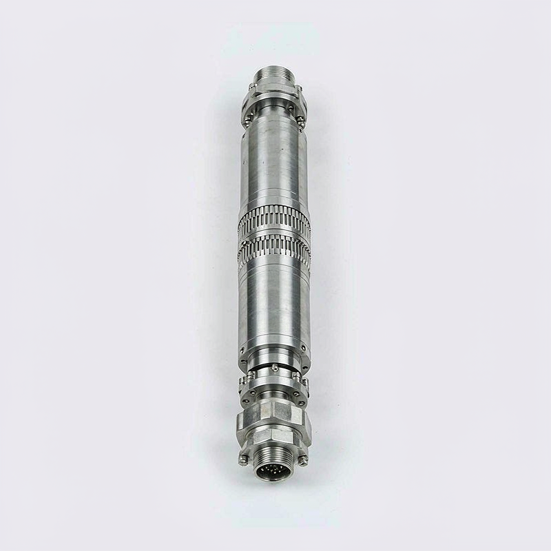
A large diameter alloy steel torsion shaft runs in preloaded precision bearings inside a finned aluminum housing. The strain gauge bridge and rotating electronics are powered inductively across an air gap, while a slotted encoder disc and stationary optical head generate speed and angle pulses. Keyed shaft ends with clamping hubs accept standard couplings, and the housing provides a wide mounting foot, lifting points and an industrial multi pin connector. An external temperature sensor can be wired into the same logger.
The 1000 Nm range is specified at better than 0.1 percent of full scale accuracy with a bandwidth of roughly one kilohertz, sufficient for torsional vibration studies. Standard bearings allow up to 4000 rpm, and the encoder delivers 360 pulses per revolution with an optional index mark. Outputs include plus or minus 10 volts, 4 to 20 milliamps and RS485 with a documented register map. Thermal zero drift is compensated, and mechanical stops limit damage if a test article locks unexpectedly.
Support the housing rigidly and use high quality flexible couplings on both sides to isolate bending; at this torque level even small misalignment produces significant side load. Confirm the shaft key fit and tightening torque before the first run, then balance the complete rotating assembly. Set the sampling rate above the highest torsional frequency of interest, wire the encoder to a counter input, and verify zero with the shaft uncoupled. Plan a warm up period for long endurance tests.
The transducer is shipped in a fitted case with a bidirectional calibration report, an encoder signal description and a coupling interface drawing. Output format and shaft end dimensions are fixed at order entry because they determine the internal electronics and machining. A matching display, data logger and coupling set can be supplied as a package. Larger ranges share the same housing footprint and mounting pattern.